Sleep modes
The reason for the sleep modes is better understood by looking at the MCU power sources).
When the external power adapter is plugged in, the MCU is fully awake and all peripherals are working non-stop. When the external power is removed, the clock needs a mechanism to still keep track of the time, but of course minimize as much as possible the power consumption to avoid draining the coin cell battery too fast.
A third situation needs to be considered: the decission of not using an exteral RTC comes with a tradeoff:
- Typical RTC chips have super low power consumption. They can keep the time for months and even years without battery replacement.
- ATmega324pb is a chip optimised for low power consumption, but it can’t reach the levels of independent RTCs. Thus, based on testing, it can only keep time for days and weeks, but not for months.
So, there’s a problem during circuit testing, assembly, packaging and shipping: if the time between battery insertion to the circuit and customer delivery is greater than weeks, then the coin cell battery will be completely drained by then.
Shipping the battery sepparately is legally and logistically much more complicated, and asking the customer to open up the clock and instert the battery is just not acceptable. Thus, a third power management case must be considered: that in which the coin cell battery is inserted, but since the power adapter is NOT detected, the MCU must go to deep sleep mode, disabling the RTC from keeping time until the customer receives the product and plugs it in for the first time. That way, battery life is preserved for much longer.
Each situation is covered separately:
External power removal:
The MCU is assumed to opperate in any of the active sytem states. The series of steps is described below:
-
Power adapter disconnect triggers the external power Pin Change Interrupt flag. The CPU will finish whatever is currently doing in any system state loop and jump to the ISR handler within 1ms.
- ISR handler checks if power is effectively removed, disables debug LED and overrides current system state to force program flow to jump back to main loop, and start executing
go_to_sleep()system state function.ISR(PCINT2_vect) { if(!EXT_PWR){ // Boost is automatically powered off (12V removed) RTC_SIGNAL_SET(LOW); // Dont use RTC LED system_state = SYSTEM_SLEEP; // GO TO SLEEP !!! } } -
sleep_modevariable passed togo_to_sleep()is one of two values:RTC_DISABLEorRTC_ENABLE(default). This determines whether the time keeping function (the RTC) remains active or not. - A sequence of steps is performed to disable all peripherals one by one, including buttons interrupts. When the sleep cause is the external power that was removed, the RTC remains active.
ports_power_save(ENABLE)configures input/output ports to avoid wasting unnecesary current.void peripherals_disable(volatile uint8_t mode) { adc_set(DISABLE); uart_set(DISABLE); buzzer_set(DISABLE); timer_leds_set(DISABLE, 0, 0, 0); timer_base_set(DISABLE); buttons_set(DISABLE); // Disable RTC only if entering POWER DOWN if(mode == RTC_DISABLE) timer_rtc_set(DISABLE); ports_power_save(DISABLE); } - Selects the right sleep mode.
SLEEP_MODE_PWR_DOWNis the deepest sleep mode.SLEEP_MODE_PWR_SAVEkeeps the RTC running. Then, go to sleep. Program execution is halted at this point. The only interrupt sources (wake up sources) enabled are RTC interrupts (to update time) and external power reconnection.if(mode == RTC_DISABLE) set_sleep_mode(SLEEP_MODE_PWR_DOWN); // Select POWER_DOWN sleep else if(mode == RTC_ENABLE) set_sleep_mode(SLEEP_MODE_PWR_SAVE); // Select POWER_SAVE sleep sleep_enable(); // Enable Sleep Mode sleep_bod_disable(); // Disable BOD when sleep sei(); sleep_cpu(); - When the CPU wakes up, the first thing it does is to service the ISR call. Then, code execution return to the point right after where it went to sleep. Then it checks for the presence of external power. If present, enables all system peripherlas, performs some system checks and resumes normal execution. If not, goes back to sleep again.
if(EXT_PWR) { step = ENABLE_SYSTEM; mode = RTC_ENABLE; } else { step = SLEEP_CPU; } - Two system checks are performed before resuming normal execution:
adc_voltages_test(), which checks normal system voltage levels, andalarm.triggeredflag, which might have been set during sleep mode (given the alarm was enabled). After that, program execution is resumed as usual.// check system voltages _delay_ms(2000); if(!adc_voltages_test()){ system_reset = TRUE; *state = SYSTEM_RESET; } else { if(alarm.triggered) *state = ALARM_TRIGGERED; else *state = SYSTEM_INTRO; }
Intentional system reset:
A general system reset can be enforced. It places the system in deep sleep mode (SLEEP_MODE_PWR_DOWN) which halts the RTC time keeping function. This is useful once the clock has been tested, the coin cell battery has been inserted, and it is desired to avoid the system from keeping time.
- Once the clock is in the normal
DISPLAY_TIMEsystem state, all three buttons should be pressed at the same time for 2 seconds. This forces a system state override where the program execution will jump toSYSTEM_RESETand will halt the RTC peripheral.// IF ALL THREE BUTTONS PRESSED DURING DELAY3, RESET SYSTEM AND GO TO SLEEP if((btnX.action) && (btnX.delay3) && (btnY.action) && (btnY.delay3) && (btnZ.action) && (btnZ.delay3)){ btnX.action = FALSE; btnY.action = FALSE; btnZ.action = FALSE; display.set = OFF; system_reset = TRUE; *state = SYSTEM_RESET; } - Once the program flow reaches
go_to_sleep(), the sequence of events is exactly as described above, with the sole exception that now the sleep mode flag is set toRTC_DISABLE, and no RTC will be active. This way, the only wake up source will be the external power reconnection.
Coin cell battery insertion:
If the coin cell battery is inserted in the circuit before it gets energized by the external power adapter, the MCU will start code execution as usual, so one of the firts tasks it must perform is to check for the existence of external power. Otherwise it should go to sleep in deep sleep mode.
/*
* Power source check:
* Look for EXT_PWR pin. If there's an external power adapter connected,
* Initialize RTC, enable Boost and all other peripherals. Run system.
* If no voltage in EXT_PWR, it means that battery has been connected first.
* In that case, do nothing and go to sleep.
*/
if(EXT_PWR) {
    sleep_mode = RTC_ENABLE;
    system_state = SYSTEM_INTRO;
    peripherals_enable();
    led_blink(3, 40);
    uart_send_string_p(PSTR("\n\rFirmware Version: "));
    uart_send_string_p(PSTR(FIRMWARE_DATE));
    uart_send_string_p(PSTR("\n\r"));
} else {
    sleep_mode = RTC_DISABLE;
    system_state = SYSTEM_SLEEP;
}
If no external power is found, some initialization tests are skipped, like factory test and voltages test, and it jumps right into the go_to_sleep() function, inside of which execution flow follows the same pattern described above.
Operation frequency
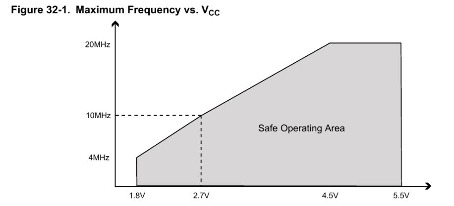
MCU operation frequency range is dependent on supply voltage. Datasheet gives:

There’s an on board 16MHz ceramic resonator. Since the MCU is expected to work with a coin cell battery voltage of about 2.7V minimum, the maximum allowed frequency is 10MHz. Nevertheless, the MCU offers only one option to prescale the external clock source: enabling a configuration fuse that sets a prescale factor of 8. At the top of main.c there’s a section for fuses configuration.
#define FUSE_BITS_LOW (FUSE_SUT_CKSEL0 & FUSE_CKDIV8)
The bit mask FUSE_CKDIV8 sets the use of the prescaler by 8. Thus, the CPU frequency is set to be 2MHz. This is also stated in config.h:
// 16MHz ceramic resonator, prescaled by 8
#define F_CPU			2000000UL
// A non-usual baud rate, but it's needed due to the low operating frequency,
// so that it may work with no errors
#define BAUD 			125000UL
As a consequence, the baud rate for serial communications is forced to be a non-standard rate of 125.000 bauds. Lower values provoke slower communication rates and generate a slight flickering on the display every second. A valid standard baud rate is 19.200, although the flickering effect is notorious.
I’ve been able to use the 125.000 baud rate using off-the-shelf usb to serial adapters and PuTTY as virtual COM port under windows. No problems whatsoever. On the other hand, I’ve not been able to use PuTTY under Linux with non-standard baud rates. I also tried minicom, but no success.
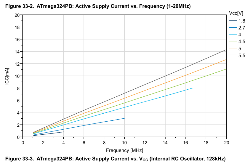
Lower CPU frequencies is also advantageous: it presents lower power consumption, although it takes more time to execute tasks and go to sleep.

Further testing might be needed in order to determine the exact power consumption of the MCU and a more accurate estimate of the coin cell battery life.