MCU peripherals
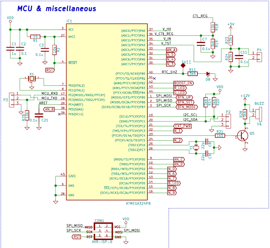
This is a list of the peripherals used:
- GPIO: including pin change interrupts
- ADC: to check system voltages.
- EEPROM: to save or read user configuration and testing results.
- UART: serial communication to communicate with PC
- Timers: events and tasks coordination. It includes RTC (using external quartz crystal) and LEDs’ PWM generation.
Some of the miscellaneus elements around the MCU are shown below.

The buzzer shown below is a piezoelectric one. Using a timer to generate 50% duty cycle PWM with variable frequency, different tones are generated.
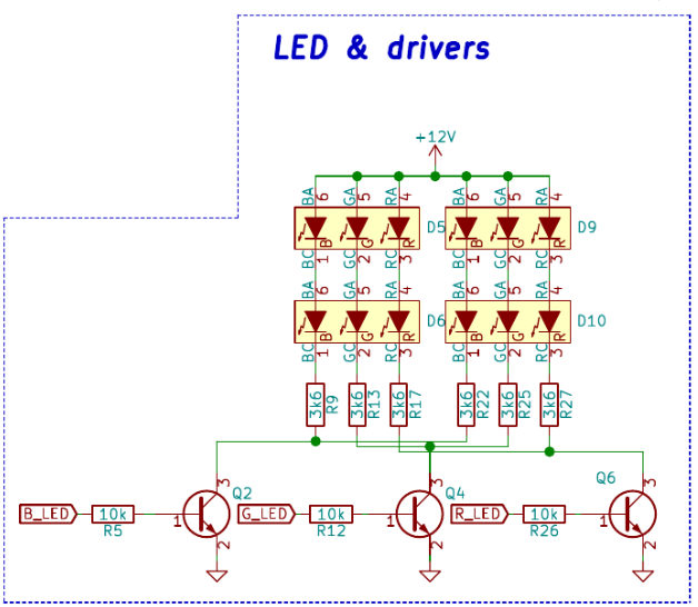
Four RGB LEDs are mounted behind every tube. They are wired as two strings of LEDs. These are also controlled by PWM generated by timers with fixed frequency, but variable duty cycle.

The I2C port was left available for any future addition or integration with I2C-based devices like temperature sensors, accelerometers, etc.